|
Current version: |
|||||||||||||||
|
|
|||||||||||||||
 |
|||
|
Features - Material Profile Definition Have you ever been frustrated with having to move or redefine material profiles whenever you want to change the slope surface? Or wondered why you cannot realistically model complex geology? Or how to include structures? Great News! The old ways are no more - GALENA introduced a better way! |
|
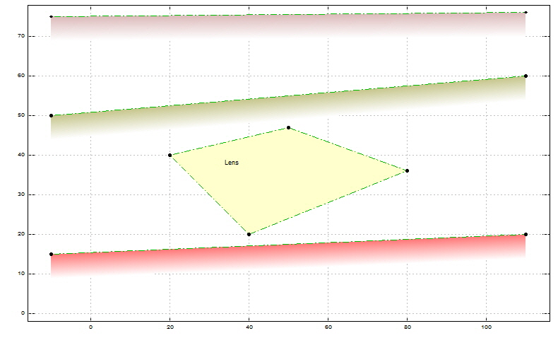
Another of GALENA's unique features is the ability to include material lenses and enclosed features - simply draw them into your model as closed polygons, and GALENA will do the rest. GALENA can also be used to model complex situations including vertical or near-vertical folding, included structures (retaining walls, sheet pile walls, etc.), dams and cofferdams. Definition of Material Profiles, Slope Surface, Phreatic Surface, Piezometric Surfaces, Non-Circular Failure Surface and Sarma Slices can either be with GALENA's CAD-style mouse line-draw function, by keyboard co-ordinate entry, or a combination of both. Definition made easy - the way it should be! |
|
The image below shows geology that includes an enclosed material lens, modelled with a closed polygon (a feature that we have been told cannot be easily modelled in other programs). The other material profiles within this model are simply defined by two points. Once the material profiles are defined a slope surface can be defined, and should it prove necessary to change the slope surface it would simply be a matter of (only) changing the slope surface... much less work than re-definition of the slope surface and the material profiles (as in most other programs). Imagine how much time would be saved, especially with more complex models. |
|||
 |
|||
|
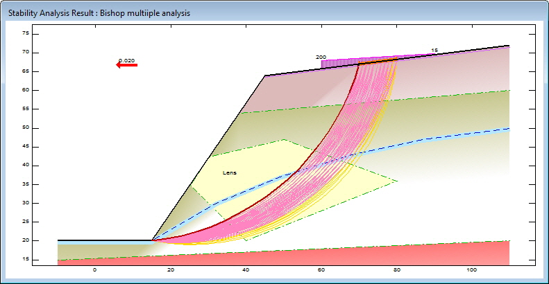
An analysis result image from the same model (after definition of a slope surface, phreatic surface, distributed load and earthquake force) is shown below, where the slope surface ‘cuts through’ the lens material (defined as a closed polygon) - only those materials within the slope are (automatically) shown. This image shows the 53 lowest FoS failure surfaces - the number of surfaces displayed is controlled interactively once the result image is displayed. |
|||
 |
|||
|
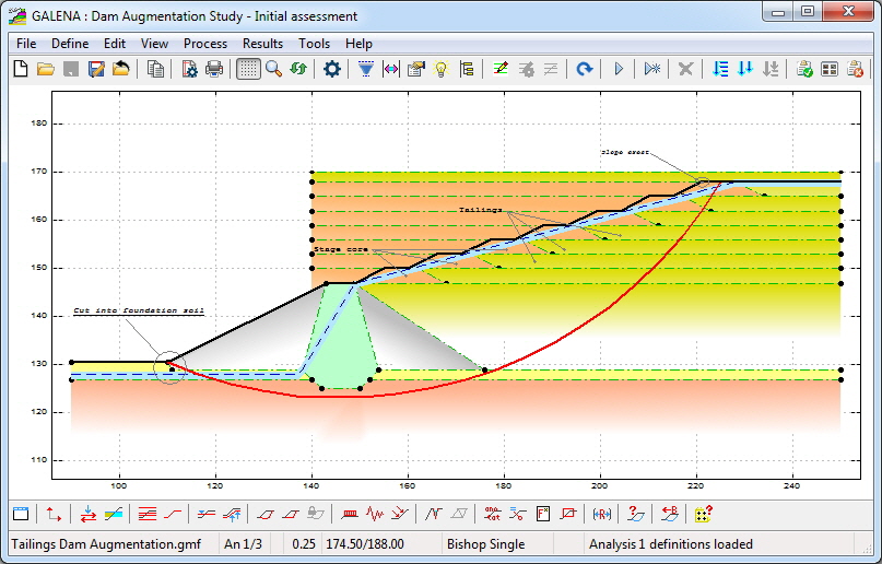
A similar approach (as described above) can be applied to other situations - the image below shows a model for a dam augmentation study, where material profiles for each level of stage core are defined by three points. The face end of each stage core profile is defined at x=140, and the back-end defined where an expected worst-case might require. The face of the stage core is defined by the slope surface, which can be adjusted independently of the stage core profiles to potentially steepen the face (depending on analysis FoS results). The back-end positions can be adjusted as necessary once a satisfactory slope face is determined. |
|||
 |
|||
|
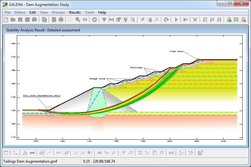
The generated result image from analysis (of the above) is shown below. This image shows the 99 lowest FoS failure surfaces - failure surfaces are colour-coded to defined Factor of Safety ranges, thereby providing an easy visual indication of results. |
|||||
 |
|||||
|
|
